Spatial Reality Capture Guide: LiDAR, Photogrammetry & 3DGS
Author: Ruumica Engineering · Spatial Reality Capture & Systems
Published: October 28, 2026 · Category: Capture Technologies & Methodology
Outdated 2D paper blueprints, manual laser tape measurements, and static site photographs introduce systematic dimensional errors that often remain hidden until prefabricated steel or MEP ductwork fails to fit on site. Modern spatial reality capture combines Mobile SLAM LiDAR, Terrestrial Laser Scanning (TLS), photogrammetry, and 3D Gaussian Splatting (3DGS) to digitize physical structures into millimeter-accurate 3D coordinate space. This engineering handbook provides chief engineers, lead architects, surveyors, and real estate asset directors with a rigorous framework for selecting the optimal scanning methodology, accuracy tier, and deliverable format.
#What Is Spatial Reality Capture and Why Does It Replace Manual 2D Surveying?
Spatial reality capture is the non-contact digitization of physical buildings, industrial facilities, and infrastructure using laser scanners and optical sensors, achieving a relative local accuracy of ±1 mm to ±15 mm and a point density exceeding 10,000 to 50,000 points/m². Unlike single-point manual measurements, reality capture systems record 640,000 to 2,000,000 coordinate points per second, eliminating human transcription errors, missed structural blind spots, and costly return site visits.
The fundamental flaw of traditional 2D manual surveying (handheld laser distometers and tape measures) is the assumption that existing walls are plumb, corners are orthogonal at 90 degrees, and floor slabs are perfectly level. In real-world architectural environments — particularly historic limestone structures, post-industrial brick conversions like Noblessner in Tallinn, or mid-century precast concrete buildings — wall plumb deviations of 25–80 mm and slab deflections of 15–45 mm are routine.
When design teams model new renovations from idealized 2D spot dimensions, severe structural and MEP clashes become inevitable during construction. Spatial reality capture replaces geometric assumptions with verifiable, continuous three-dimensional ground truth:
- Complete Volumetric Coverage: Every square meter of the asset is sampled by thousands of laser pulses, capturing load-bearing trusses, overhead pipe runs, and irregular masonry mortar joints simultaneously.
- Immutable As-Built Record: A registered point cloud paired with a 3DGS visual twin provides a timestamped, legally verifiable record of site conditions prior to demolition, renovation, or lease handover.
- Rapid Field Execution: Capturing a complex 1,500 m² commercial floor or industrial hall takes 35–50 minutes using mobile SLAM instrumentation, requiring zero operational downtime.
- Direct CAD & BIM Integration: Cleaned spatial datasets import directly into Autodesk Revit, Graphisoft ArchiCAD, AutoCAD, or QCAD Pro to drive parametric Scan-to-BIM & As-Built Modeling workflows.
#Comparing the 4 Core Technologies: TLS, Mobile SLAM LiDAR, Photogrammetry & 3DGS
The four primary reality capture methodologies divide into active time-of-flight laser systems (Terrestrial Laser Scanning at ±1–2 mm precision and Mobile SLAM LiDAR at capture speeds up to 2,500 m²/hour) and optical radiometric methods (Photogrammetry and 3D Gaussian Splatting, which rasterizes photorealistic volumetric scenes at 60+ FPS). Selecting the right instrument depends on whether your primary engineering deliverable is sub-millimeter structural verification, parametric BIM geometry, or real-time web visualization.
To evaluate these systems objectively, we first establish their canonical engineering definitions.
1. Terrestrial Laser Scanning (TLS)
Stationary tripod-mounted scanners (such as Leica RTC360, Faro Focus, or Trimble X9) emit high-frequency laser pulses to measure distance via Time-of-Flight (ToF) or phase-shift modulation across a full panoramic dome. TLS remains the metrology benchmark for static single-station accuracy (±1.0 mm to ±2.0 mm) at ranges up to 130–350 meters. However, because laser beams travel strictly in straight lines-of-sight, capturing a partitioned multi-room building requires moving and leveling the tripod dozens or hundreds of times.
2. Mobile SLAM LiDAR
Mobile SLAM LiDAR systems (such as the XGRIDS Lixel L2 Pro or NavVis VLX) decouple the laser sensor from the static tripod. By fusing multi-beam LiDAR (320,000–640,000 pts/sec) with an industrial-grade Inertial Measurement Unit (IMU), visual odometry cameras, and ground control targets, SLAM algorithms solve the scanner's 6-DoF trajectory dynamically while the operator walks through the site. This achieves ±2 mm to ±5 mm relative indoor accuracy while operating up to 10x faster on complex job sites. For a dedicated field benchmark, read Mobile SLAM LiDAR vs. Terrestrial Laser Scanning (TLS): Accuracy vs. Speed on Job Sites.
3. Terrestrial & Aerial Photogrammetry
Photogrammetry derives 3D coordinates by triangulating matching pixel features across hundreds of overlapping photographs. While effective for textured building facades, roofs, and earthworks, photogrammetry fails on featureless white drywall, glass partitions, dark mechanical ceilings, and thin steel cabling where feature-matching algorithms cannot lock onto distinct textures.
4. 3D Gaussian Splatting (3DGS) & Spatial Cameras
3D Gaussian Splatting — particularly when anchored by LiDAR depth priors or dedicated spatial hardware like the XGRIDS PortalCam — eliminates the broken-mesh artifacts of traditional photogrammetry. Instead of forcing complex real-world lighting and geometry into rigid polygon triangles, 3DGS optimizes millions of continuous 3D Gaussian ellipsoids in space. Each splat stores a 3D position $(x,y,z)$, a $3\times 3$ covariance matrix defining scale and rotation, an opacity value ($\alpha$), and Spherical Harmonics (SH) coefficients that reproduce view-dependent reflections, glass refraction, and fine structural wires at 60+ FPS. Dive deeper in What is 3D Gaussian Splatting (3DGS) and How Does It Compare to Photogrammetry Meshes?.
Engineering Comparison Matrix: Point Density, Accuracy & Capture Speed
| Parameter / Metric | Terrestrial Laser (TLS) | Mobile SLAM LiDAR | Photogrammetry (SfM) | 3D Gaussian Splatting (3DGS) |
|---|---|---|---|---|
| Relative Local Accuracy | ±1.0 mm to ±2.0 mm | ±2.0 mm to ±5.0 mm | ±5.0 mm to ±25.0 mm | ±3.0 mm to ±10.0 mm (LiDAR-anchored) |
| Global Accuracy (with GCP/RTK) | ±2.0 mm to ±4.0 mm | ±5.0 mm to ±15.0 mm | ±15.0 mm to ±50.0 mm | ±5.0 mm to ±15.0 mm (SLAM-fused) |
| Point / Primitive Density | 50,000 – 250,000+ pts/m² | 15,000 – 60,000 pts/m² | 5,000 – 30,000 vertices/m² | 1,500,000 – 6,000,000 splats / scene |
| Field Capture Time (1,000 m²) | 4.0 – 6.5 hours (45–80 setups) | 25 – 40 minutes (continuous walk) | 2.0 – 3.5 hours (800+ photos) | 20 – 35 minutes (spatial walk) |
| Glass, Reflections & Thin Wires | Poor (requires manual cleanup) | Good (multi-return + intensity filter) | Critical failure (torn meshes) | Exceptional (Spherical Harmonics) |
| Primary Native Formats | .e57, .rcp, .las |
.las, .laz, .e57 |
.obj, .fbx, .glb |
.sog, .spz, .ply |
| Primary AEC / CRE Use Case | Industrial plant metrology, steel QA | Scan-to-BIM, floor plans, MEP audits | Roof envelopes, orthophotos, terrain | Interactive digital twins, remote audits |
#How Raw Scan Data Is Cleaned, Registered, and Georeferenced (L-EST97)
Post-processing transforms raw sensor trajectories into a unified, survey-grade point cloud through Iterative Closest Point (ICP) registration, achieving a mean absolute registration error of ≤ 3.0 mm with a minimum trajectory overlap of ≥ 70%. When projects require cadastral or municipal integration in Estonia, the local coordinate cloud is mathematically transformed into the national L-EST97 (EPSG:3301) planar coordinate system and EH2000 vertical datum.
Raw field captures inevitably contain environmental noise: moving site personnel, multipath laser reflections bouncing off mirrors or double-glazed windows, and airborne construction dust. Feeding an uncleaned point cloud directly into Revit or ArchiCAD slows down workstations and introduces modeling errors.
Allround's engineering post-processing pipeline executes four mandatory validation stages:
1. SLAM Trajectory Optimization & Loop Closure: As a mobile scanner traverses long corridors or multi-story stairwells, tiny IMU integration errors accumulate as trajectory drift. By executing deliberate figure-eight paths and closed loops in the field, the SLAM solver identifies revisited architectural geometry and distributes residual drift globally across the pose graph, locking relative indoor accuracy to ±2–3 mm.
2. Statistical Outlier Removal (SOR) & Multipath Filtering: Automated spatial filters in CloudCompare and custom Python pipelines evaluate neighborhood point distributions, stripping out transient pedestrians, airborne dust particles, and ghost reflections behind glass panes while preserving sharp structural edges.
3. Geodetic Coordinate Transformation (L-EST97 / EH2000): For projects requiring integration with site topography or Estonian Building Registry (EHR) & Maa-amet compliance, physical survey targets (GCPs) are measured using a total station or RTK-GNSS rover. The registered point cloud is anchored via a 6-DoF rigid-body transformation matrix:
$$\\mathbf{P}_{\\text{L-EST97}} \= s \\cdot \\mathbf{R} \\cdot \\mathbf{P}_{\\text{local}} + \\mathbf{T}$$
where $R$ represents the $3\times 3$ orthogonal rotation matrix, $T$ is the translation vector $[T_X, T_Y, T_Z]^T$, and $s$ is the scale factor ($s=1.0000$ for calibrated LiDAR systems).
4. Spatial Decimation & Octree Indexing: To keep CAD/BIM viewports responsive while preserving edge fidelity, the master cloud is spatially subsampled to uniform spacing (e.g., 2 mm or 5 mm grid spacing for .e57 / .rcp) and compiled into progressive octree chunks for browser streaming. For a complete breakdown of registration math, read Point Cloud Density, Noise, and Registration: How Raw Scan Data is Cleaned and Aligned.
#Verifiable Field Proof of Work: Noblessner Shipyard Conversion Benchmark
At Allround, engineering authority is demonstrated through verifiable field datasets rather than stock renders. The visual below documents the interior capture of the historic Noblessner industrial conversion in Tallinn, combining mobile SLAM LiDAR and optical spatial cameras to record structural geometry prior to BIM reconstruction.
Field Capture Telemetry (Noblessner Shipyard Conversion)
- Scanning Hardware: XGRIDS Lixel L2 Pro (Mobile SLAM LiDAR) + XGRIDS PortalCam (Spatial Camera).
- Registration Residuals: Mean Absolute Error (MAE) ≤ 2.8 mm, trajectory overlap 78%.
- Point Cloud Density: 32,400 pts/m² (cleaned structural
.lazarchive). - Coordinate System: L-EST97 (EPSG:3301) / EH2000 national vertical datum.
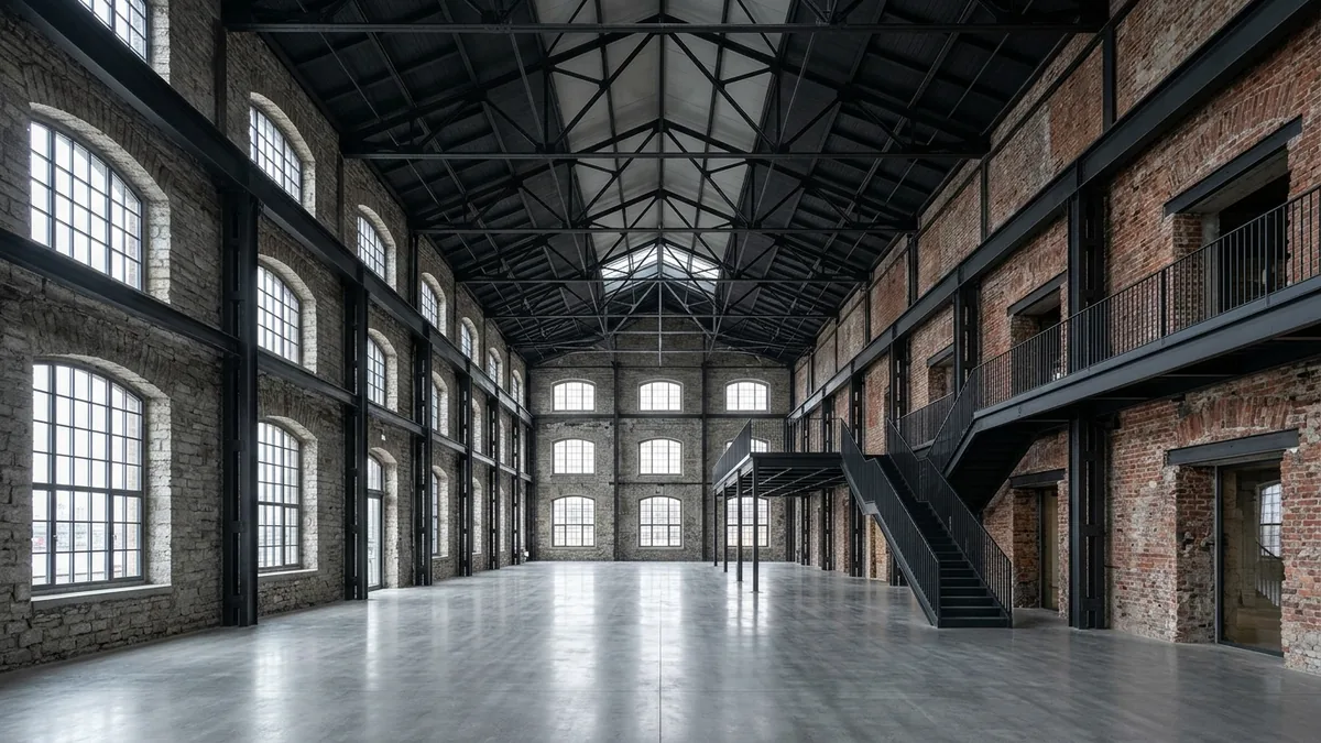
Figure 2: Interior reality capture verification of the Noblessner shipyard conversion in Tallinn (Mean Absolute Error MAE ≤ 2.8 mm in national coordinate system L-EST97).
#Decoding 3D Deliverable Formats: E57, LAS/LAZ, PLY, SOG, and SPZ
Selecting the right 3D file format dictates both storage overhead and software compatibility: an uncompressed E57 archive of a 100 m² interior scan requires approximately 6.5–9.0 GB, a lossless compressed LAZ file reduces that identical dataset to 380–450 MB (a \~95% size reduction), and modern web-ready 3DGS formats (SOG and SPZ) compress the full volumetric radiance field down to 25–45 MB. Specifying exact deliverable formats in your procurement scope prevents bottlenecks where design workstations choke on multi-gigabyte raw exports.
The benchmark table below illustrates file sizes and software compatibility for a standardized 100 m² high-density reality capture dataset:
| File Format | Standard / Architecture | Benchmark Size (100 m²) | Stored Spatial Payload | Primary Compatible Software |
|---|---|---|---|---|
.E57 |
ASTM E2807 (Binary + XML) | 8.4 GB | XYZ, RGB, return intensity, surface normals, 360° panoramas | Autodesk ReCap/Revit, ArchiCAD, CloudCompare, Bentley |
.LAS / .LAZ |
ASPRS LiDAR Standard | 4.2 GB (LAS) / 420 MB (LAZ) | XYZ, RGB, intensity, point classification, GPS timestamp | QGIS, Civil 3D, CloudCompare, PotreeConverter |
.RCP / .RCS |
Autodesk ReCap Indexed | 3.1 GB | Spatially indexed octree point cloud for native Autodesk load | Autodesk Revit, AutoCAD, Navisworks, Civil 3D |
.PLY (3DGS) |
Binary Splat Payload | 650 MB – 1.2 GB | XYZ, 3D scale, quaternion rotation, opacity, 45 SH coefficients | SuperSplat, Postshot, Blender (3DGS), LixelStudio |
.SOG / .SPZ |
Spatially Ordered / Compressed Gaussians | 28 MB – 42 MB | Quantized Gaussian ellipsoids, octree LoD chunks, SH1/SH2 | view.ruumica.com, Spark WebGL/WebGPU, PlayCanvas |
.IFC / .RVT / .DXF |
ISO 16739 BIM / 2D CAD | 15 MB – 85 MB | Parametric walls, slabs, structural columns, 2D plans (LOD 200–350) | Revit, ArchiCAD, Tekla, Solibri, QCAD Pro, AutoCAD |
For a complete engineering breakdown of compression ratios and CAD import workflows, read 3D File Formats Decoded: E57, LAS/LAZ, PLY, and SPZ Explained for Clients and Engineers.
#Overcoming Field Capture Challenges: Glass, Low Light, and Nordic Weather
Adverse optical and environmental conditions — such as floor-to-ceiling curtain glazing, mirrors, unlit mechanical basements, rain-slicked asphalt, and wind-blown foliage — can degrade uncalibrated scan accuracy by ±25–50 mm. Mitigating these artifacts requires hardware multi-return filtering, controlled exposure bracketing, and strict adherence to indoor vs. outdoor reality capture field protocols.
Across Baltic and Nordic job sites, our field engineers account for four primary physical phenomena:
- Reflective Glazing & Mirrors (Multipath Interference): When a laser pulse strikes architectural glass at an oblique angle, part of the energy reflects specularly while part penetrates the pane, creating phantom points mirrored behind the wall. We eliminate these artifacts using return-intensity thresholding in SLAM processing while utilizing 3DGS Spherical Harmonics to render realistic glass reflections in the visual twin.
- Pitch-Black Basements, Vaults & Utility Shafts: Because LiDAR is an active laser illumination technology (operating at 905 nm or 1550 nm wavelengths), it captures structural geometry with 100% accuracy in complete darkness. When synchronized colorized point clouds or 3DGS models are required in unlit spaces, diffused high-CRI LED arrays are mounted directly to the capture rig.
- Low-Angle Nordic Sun & Wet Surfaces: Autumn and winter conditions in Estonia introduce extreme low-angle solar glare alongside wet dark surfaces that absorb near-infrared laser energy. Exterior facade captures are scheduled under diffused overcast Baltic daylight to guarantee uniform radiometric exposure.
- Sub-Zero Thermal Stability: Operating in sub-zero temperatures ($-10°C$ to $-20°C$) causes thermal drift in consumer cameras. Survey-grade SLAM and TLS instruments incorporate internal thermal compensation and heated optical assemblies to maintain millimeter ranging consistency.
#Decision Framework: Selecting the Right Reality Capture Workflow
Choosing the optimal capture workflow comes down to three engineering criteria: required dimensional tolerance (mm), site area and spatial complexity (m²), and downstream software consumption (CAD/BIM vs. browser digital twin). For the majority of commercial renovations and heritage retrofits, a hybrid single-mobilization deployment combining Mobile SLAM LiDAR with 3DGS delivers the highest return on investment.
Use this engineering specification matrix to scope your project:
1. Architectural Renovation, MEP Coordination & As-Built BIM:
- Recommended Method: Mobile SLAM LiDAR anchored to surveyed control targets.
- Deliverables: Registered
.e57/.lazpoint cloud, 2D.dxf/.dwgfloor plans and sections, or a parametric Scan-to-BIM model specified at LOD 200, 300, or 350.
2. Heritage Conservation & Historic Limestone/Timber Documentation:
- Recommended Method: High-density SLAM LiDAR + 3DGS volumetric capture.
- Deliverables: Wall deformation heatmaps, true orthophoto elevations, and sub-centimeter heritage archives (see Heritage Conservation & Renovation: Sub-Centimeter Reality Capture).
3. Commercial Real Estate Marketing, Remote Investor Due Diligence & FM:
- Recommended Method: 3D Gaussian Splatting (3DGS) web digital twin.
- Deliverables: Zero-latency interactive browser walkthrough hosted on
view.ruumica.com(explore our guide on Interactive 3D & Digital Twins: Real-Time Spatial Systems).
4. Post-Construction QA, Concrete Slab Flatness & Municipal Permits (EHR):
- Recommended Method: High-density LiDAR elevation auditing and georeferenced surveying.
- Deliverables: Floor Flatness and Deflection Analysis heightmaps (0.5 mm contours) and EHR-compliant as-built layouts.
#Related Engineering Handbooks & Guides
This handbook serves as the cornerstone reference for Allround's Capture Technologies & Methodology cluster. Explore our specialized technical deep dives and companion engineering handbooks below.
Specialized Deep Dives in Capture Technologies & Data Processing
| Specialized Technical Article | Engineering Focus & Practical Takeaways |
|---|---|
| Mobile SLAM LiDAR vs. Terrestrial Laser Scanning (TLS): Accuracy vs. Speed on Job Sites | SLAM loop-closure drift correction, Ground Control Points (GCP), and 1,200 m² industrial field telemetry (35 min vs. 6 hours). |
| What is 3D Gaussian Splatting (3DGS) and How Does It Compare to Photogrammetry Meshes? | Rasterizing continuous 3D ellipsoids at 60 FPS, Spherical Harmonics lighting, and capturing glass reflections and thin steelwork. |
| Point Cloud Density, Noise, and Registration: How Raw Scan Data is Cleaned and Aligned | Statistical outlier filtering (SOR), Iterative Closest Point (ICP) registration, and L-EST97 / EH2000 coordinate transformation. |
| Indoor vs. Outdoor Capture Challenges: Overcoming Reflective Glass, Low Light, and Foliage | Mitigating laser multipath reflections on glazing, dynamic exposure bracketing, and operating in Nordic winter conditions. |
| 3D File Formats Decoded: E57, LAS/LAZ, PLY, and SPZ Explained for Clients and Engineers | Compression benchmarks (8.4 GB E57 vs. 38 MB SPZ) and direct compatibility across Revit, ArchiCAD, AutoCAD, and WebGL viewers. |
Companion Ruumica Engineering Handbooks
| Handbook Title & Direct Link | Core Engineering Focus & Deliverables |
|---|---|
| Scan-to-BIM & As-Built Modeling: The Field Guide for Architects and Engineers | Converting point clouds into parametric Revit & IFC models (LOD 200–350), tolerance verification, and building registry compliance. |
| Interactive 3D & Digital Twins on the Web: 3DGS and WebGL in Architecture | Real-time 60 FPS spatial walkthroughs, client-side browser streaming, and high-fidelity reality capture delivery. |
| Reality Capture Project Planning: Scope, Budgeting, and Site Preparation | Engineering RFP drafting, square-meter pricing variables, and site mobilization checklist for facility managers. |
Need a survey-grade point cloud, a parametric Scan-to-BIM deliverable, or an interactive spatial model for your next project in Estonia or the Nordics? Contact Ruumica Engineering directly at info@ruumica.com or explore our projects.