Scan-to-BIM & As-Built Modeling: The Complete Practical Handbook
Author: Ruumica Engineering · Spatial Reality Capture & Systems
Published: October 28, 2026 · Category: As-Built Verification & Building Modeling
Designing building renovations, industrial retrofits, or heritage restorations from legacy 2D paper blueprints and manual spot measurements leads directly to costly on-site clashes where prefabricated steel, curtain facades, and HVAC ductwork fail to fit existing structures. Scan-to-BIM eliminates this risk by translating millimeter-accurate laser-scanned point clouds into intelligent, parametric 3D Building Information Models (LOD 200 to LOD 350) natively in Autodesk Revit, Graphisoft ArchiCAD, and open IFC formats. This engineering handbook provides BIM managers, restoration architects, general contractors, and property developers with a definitive specification guide for procuring, auditing, and executing as-built BIM deliverables.
#What Is Scan-to-BIM and Why Does It Replace Legacy 2D Renovation Workflows?
Scan-to-BIM is the engineering workflow of capturing physical buildings with 3D laser scanners (Mobile SLAM LiDAR or Terrestrial Laser Scanning) and translating the registered point cloud into parametric 3D BIM geometry with a modeling tolerance of ±3 mm to ±15 mm. Unlike dumb polygon meshes, a Scan-to-BIM deliverable consists of intelligent, object-oriented building components — walls, structural slabs, steel trusses, and MEP pipe runs — complete with dimensional parameters, material metadata, and relational hosting.
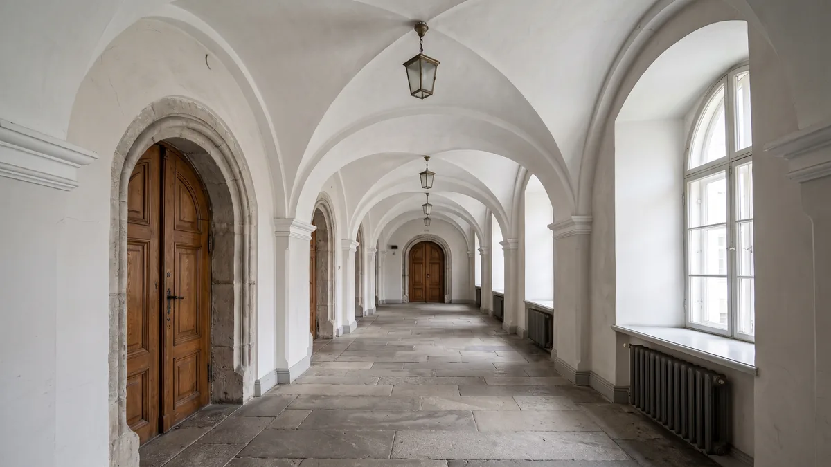
Across Baltic and Nordic building stock — ranging from 19th-century neoclassical university buildings in Tartu and medieval limestone walls in Tallinn Old Town to Soviet-era precast concrete industrial plants — the physical structure never matches archival blueprints. Decades of foundation settlement, structural slab deflection (20–55 mm), and undocumented tenant modifications render legacy 2D drawings unreliable for engineering design.
Deploying a verified Scan-to-BIM baseline prior to schematic and detailed design unlocks four measurable project advantages:
- Proactive Clash Elimination: Mechanical, electrical, and plumbing (MEP) engineers route new ductwork and piping around actual structural trusses and bowed masonry walls, preventing five-figure change orders during site installation (read How Scan-to-BIM Eliminates Clashes and Costly Rework in Renovation Projects).
- Accurate Quantity Takeoffs (QTO) & Tenders: Because parametric walls, structural openings, and floor areas reflect physical reality, material and facade procurement variance drops below 1–2%.
- Off-Site Prefabrication Confidence: Structural steel assemblies, modular glazing panels, and timber roof elements can be fabricated off-site directly from the as-built model with guaranteed anchor bolt alignment.
- Automated 2D CAD Extraction: All required 2D floor plans, structural sections, and facade elevations (
.dwg/.dxf) are extracted directly from a single coordinated 3D source of truth.
#Specifying Level of Development (LOD 200 vs 300 vs 350) Without Overpaying
The Level of Development (LOD) specification dictates both the geometric precision and non-graphical metadata density of an as-built BIM model: LOD 200 captures approximate volumetric envelopes at ±20–30 mm tolerance, LOD 300 delivers precise architectural and structural geometry at ±5–10 mm, and LOD 350 models structural connections, flanges, and MEP hangers at ±3–5 mm accuracy. The most cost-effective procurement strategy is a hybrid LOD specification — contracting general architectural shells at LOD 300 while specifying exposed mechanical rooms and structural tie-in zones at LOD 350.
A frequent procurement mistake is requesting "LOD 400 across the entire building" in tender documents. In existing buildings, LOD 400 (fabrication-level detailing) is financially wasteful and physically impossible via non-destructive laser scanning, as optical and laser sensors cannot see rebar inside poured concrete or framing studs behind closed drywall.
Engineering Specification Matrix: LOD 200 vs. LOD 300 vs. LOD 350 for As-Built BIM
| Building System / Metric | LOD 200 (Volumetric / Schematic) | LOD 300 (Standard As-Built Design) | LOD 350 (Detailed Coordination & Tie-Ins) |
|---|---|---|---|
| Point Cloud Modeling Tolerance | ±15 mm to ±30 mm | ±5 mm to ±10 mm | ±3 mm to ±5 mm (critical tie-in nodes) |
| Walls, Columns & Slabs | Nominal thickness, orthogonal (90°) alignment, averaged floor heights | Actual thickness, exact opening locations, major plumb deviations (>15 mm) modeled | True wall warping, cornices, structural corbels, base plates, and slab deflection profiles |
| Windows & Doors | Generic wall opening with simplified placeholder panel | Exact frame dimensions, mullion divisions, glazing planes, and swing direction | Detailed frame profiles, sills, reveals, hardware clearances, and threshold transitions |
| Structural Steel & Timber | Generic bounding-box extrusion | Exact standard section profile (e.g., HEA/IPE) or measured timber cross-section & slope | Exact profile + gusset plates, bolted flanges, stiffeners, purlins, and anchor plates |
| MEP Systems (HVAC, Piping, Elec) | Primary riser zones & main trunks only (Ø > 150 mm) | Pipes & ducts Ø ≥ 50 mm, major equipment clearances | Pipes Ø ≥ 20 mm, insulation thickness, valves, flanges, cable trays, and structural hangers |
| Relative Modeling Effort & Cost | 1.0x (Baseline) | 1.6x – 2.2x (Industry Standard) | 2.8x – 4.0x (High-Density Engineering) |
| Primary Project Application | Feasibility studies, massing, net floor area audits | Architectural renovation, heritage permits, EHR filings | Detailed MEP coordination, clash detection, steel prefabrication |
For a granular element-by-element breakdown and cost optimization guide, read Level of Detail (LOD 200 vs 300 vs 350): Specifying As-Built BIM Without Overpaying.
#From Point Cloud to Revit & ArchiCAD: The 5-Stage Production Pipeline
A rigorous Scan-to-BIM production workflow executes five sequential engineering stages: field capture and geodetic control, point cloud registration and indexing (.rcp/.e57), coordinate datum and work-plane locking, cross-sectional parametric modeling, and automated surface-deviation QA/QC. Following this structured pipeline guarantees that the delivered .rvt, .pln, or .ifc model opens cleanly in the design team's authoring environment without coordinate drift or broken geometry.
Allround's engineering pipeline from raw laser scan to validated BIM deliverable (detailed further in From Point Cloud to Revit & ArchiCAD: Step-by-Step As-Built Modeling Pipeline) follows five strict steps:
1. Targeted Field Mobilization (SLAM LiDAR + TLS): Field engineers scan the asset according to the contracted LOD matrix. When above-ceiling MEP routing (LOD 350) is required, ceiling tiles are opened at strategic intervals to capture hidden plenum spaces. All SLAM trajectories are closed via figure-eight loops, achieving a registration residual of ≤ 3.0 mm.
2. Outlier Filtering & Octree Indexing: Transient site clutter, pedestrians, and specular glass reflections are stripped using Statistical Outlier Removal (SOR). The cleaned point cloud is indexed into native Autodesk ReCap (.rcp/.rcs) and vendor-neutral .e57 chunks segmented by floor level.
3. Geodetic Datum & Project Base Point Locking: Before placing a single wall, the coordinate architecture is locked. When cadastral alignment is required in Estonia, the BIM Survey Point is anchored to national L-EST97 (EPSG:3301) and EH2000 elevation benchmarks, while the Project Base Point is rotated to align orthogonally with the building's primary structural grid to prevent floating-point precision errors inside Revit or ArchiCAD.
4. Dual-Sided Cross-Section Extraction: BIM engineers never trace walls freehand in perspective view. Thin 10–20 mm horizontal and vertical point cloud slices (section boxes) are cut across levels. Wall thicknesses are derived simultaneously from both interior room surfaces, immediately revealing hidden structural chases, acoustic cavities, or masonry tapering.
5. Automated Deviation Analysis (QA/QC): The completed parametric model is overlaid against the master point cloud to compute a 3D surface deviation map. Any structural element exceeding the contracted tolerance threshold (e.g., > 8 mm for LOD 300) is flagged and corrected prior to client handover.
#Engineering Rules for Bowed Walls, Out-of-Plumb Columns, and Heritage Structures
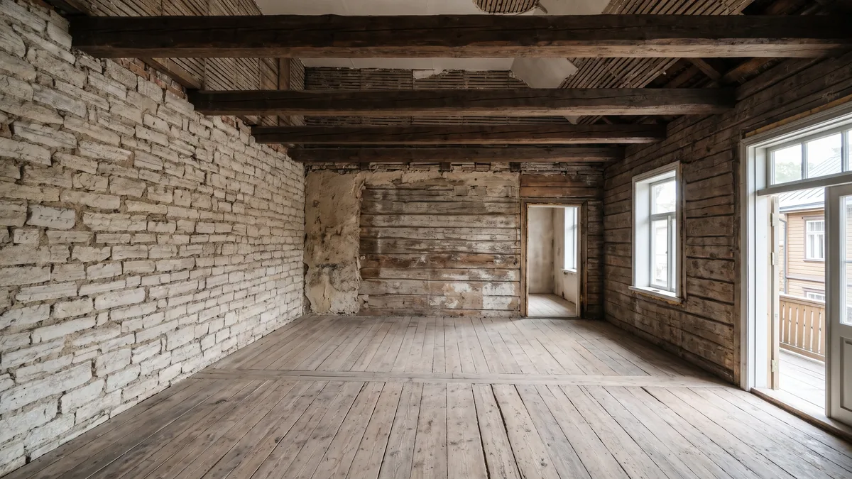
Because no physical building is perfectly rectilinear, every Scan-to-BIM project must establish an explicit orthogonalization threshold in the BIM Execution Plan (BEP): walls and columns deviating by ≤ 10–15 mm are typically modeled as plumb and orthogonal (90°), whereas structural elements leaning or bowing by > 15 mm are modeled true-to-scan using slanted walls, segmented profiles, or custom in-place geometry. Failing to define this rule upfront can result in a model where every wall sits at an awkward 89.74-degree angle, breaking downstream dimension strings and standard family hosting in Revit.
We apply three core modeling rules to handle real-world structural irregularities:
- Tolerance-Driven Orthogonalization (Idealized vs. True-to-Scan): In modern commercial offices and residential apartments where construction variance falls within standard tolerances (±10 mm), walls are snapped to orthogonal axes and standard nominal thicknesses. This ensures clean 2D construction documentation and predictable BIM scheduling.
- Capturing Critical Structural Deviations: When a load-bearing masonry wall leans by 35 mm or a concrete warehouse floor sags by 28 mm at mid-span, forcing an idealized flat element hides critical engineering risk. We model slanted walls natively and supplement the BIM file with a high-resolution Floor Flatness and Deflection Analysis heightmap (0.5 mm contours).
- Heritage Conservation & Irregular Masonry (Muinsuskaitse): For protected historic monuments — such as vaulted limestone cellars in Tartu, timber villas in Kadriorg, or industrial heritage in Rotermann — straightening walls destroys historical truth. We combine multi-segment parametric profiles, custom NURBS/in-place families, and high-resolution true orthophotos (explore Heritage Conservation & Renovation: Sub-Centimeter Reality Capture for Historic Buildings).
#Verifiable Field Proof of Work: Rotermann Limestone & Steel Benchmark
The true test of an as-built modeling workflow is how accurately it captures complex, irregular historical geometry. The interactive 3D spatial model below (rotermanni) showcases a multi-level historic limestone and Corten steel studio in Tallinn's Rotermann Quarter, captured as a high-precision foundation for Scan-to-BIM documentation.
Field Capture Telemetry & BIM Specifications (rotermanni)
- Capture Methodology: Hybrid Mobile SLAM LiDAR + 3D Gaussian Splatting (3DGS).
- Registration Accuracy: Root Mean Square (RMS) error ≤ 2.5 mm, loop closure overlap 82%.
- Measured Structural Deviation: Historic limestone wall vertical plumb deviation of 18–42 mm over floor height (captured for LOD 300–350 modeling).
- Deliverable Package: Registered
.e57/.lazpoint cloud, parametric.rvt/.ifcmodel, and the browser-streamed.sog/.spzvisual twin below.
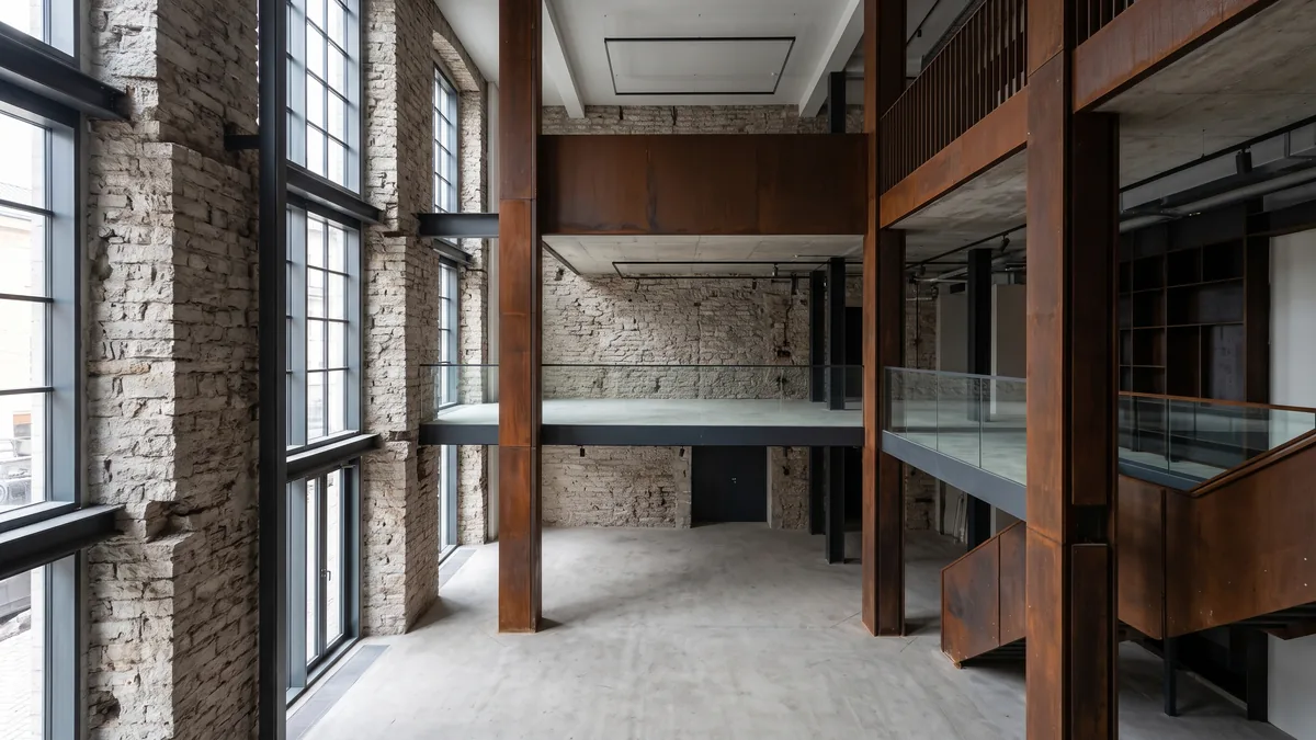
Figure 3: Historic limestone and Corten steel studio conversion in Tallinn's Rotermann Quarter. Laser-scanned irregular masonry and roof truss geometry for LOD 300–350 as-built modeling.
#Software Interoperability, OpenBIM (IFC), and Estonian BIM Standards (ÜBN)
A production-grade Scan-to-BIM deliverable must seamlessly support both native authoring platforms (Autodesk Revit .rvt, Graphisoft ArchiCAD .pln) and vendor-neutral OpenBIM standards (IFC 2x3 / IFC 4.3, ISO 19650), alongside Estonia's national Common BIM Requirements (Ühtsed BIM Nõuded — ÜBN). Public-sector authorities (such as State Real Estate Ltd / Riigi Kinnisvara AS) and institutional developers require that all as-built elements carry standardized classification codes (CCI-EE or Uniclass), strict storey containment, and synchronized shared coordinates.
The matrix below outlines the primary Scan-to-BIM deliverable formats and their role across the AEC lifecycle:
| Deliverable Format | Primary Software Ecosystem | Parametric Editability | Core Engineering & Compliance Role |
|---|---|---|---|
.RVT (Native Revit) |
Autodesk Revit (2022–2026) | Full (Native system & loadable families) | Direct architectural, structural, and MEP renovation authoring in Revit. |
.PLN / .MOD |
Graphisoft ArchiCAD | Full (Native walls, slabs, beams & GDL objects) | Architectural restoration design and quantity takeoffs in ArchiCAD. |
.IFC (IFC 2x3 / IFC 4) |
OpenBIM (Solibri, Tekla, Trimble Connect, Dalux) | Reference Geometry + Locked Semantic Attributes | Federated model coordination, clash detection, and Estonian ÜBN / RKAS handover. |
.DWG / .DXF (2D/3D) |
AutoCAD, QCAD Pro, BricsCAD, Civil 3D | 2D Vector Polylines, Layers & Blocks | As-built floor plans, sections, elevations, and Estonian Building Registry (EHR) permits. |
.RCP / .E57 / .LAZ |
All BIM/CAD Platforms + CloudCompare | Immutable Registered Point Cloud | Ground-truth verification underlay linked directly inside the BIM authoring file. |
To eliminate handoff friction, Allround delivers a complete multi-format engineering bundle: the native authoring model (.rvt or .pln), a validated .ifc coordination export, extracted 2D .dwg/.dxf drawings, and the registered .e57/.laz point cloud for direct verification inside your viewport.
#Related Engineering Handbooks & Guides
Explore our comprehensive engineering handbooks covering spatial reality capture, interactive 3D digital twins, and project planning:
| Handbook Title & Direct Link | Core Engineering Focus & Deliverables |
|---|---|
| Spatial Reality Capture Guide: LiDAR, Photogrammetry & 3DGS | Comparing Terrestrial Laser Scanning (TLS), Mobile SLAM LiDAR, and 3DGS radiance fields for AEC site verification. |
| Interactive 3D & Digital Twins on the Web: 3DGS and WebGL in Architecture | Real-time 60 FPS spatial walkthroughs, client-side browser streaming, and high-fidelity reality capture delivery. |
| Reality Capture Project Planning: Scope, Budgeting, and Site Preparation | Engineering RFP drafting, square-meter pricing variables, and site mobilization checklist for facility managers. |
Ready to commission a survey-grade point cloud or a parametric LOD 200–350 Scan-to-BIM model in Estonia, Latvia, or Finland? Contact Ruumica Engineering at info@ruumica.com or review our services.